Estimating the ‘right’ amount of raw material for purchase is one of the biggest headaches of metal product fabrication companies. About 60% of their total production budget is spent on raw materials. Thus, every piece of scrap not only represents material waste but also a waste of logistics and financial resources. And the amount of waste or optimization in material purchase depends on the accuracy of manufacturing shop drawings.
Market research shows that the global demand for metal fabrication comes primarily from building construction, architecture, building components and piping. This demand is growing at a rate of >4% CAGR. And for metal fabricators, reducing scrap is a key to remaining competitive.
Metal fabrication shop drawings have detailed information needed to convey the exact design intent for work teams and to reduce rework. They serve as a single source of truth across product stakeholders to close design communication gaps and remove inconsistencies.
Operational requirements of metal product manufacturers

- Following a standard sequence of manufacturing operations using advanced machines
- Detailed shop drawings for accurate and precise manufacturing
- BOMs for multi-part assemblies
- Agile inventory management
- Addressing all dynamic manufacturing parameters on the shop floor
Metal shop drawings encompass the information in a single CAD file for all stakeholders. But preparing accurately detailed shop drawings is not easy. So, here’s a list of the top five pieces of information you must include in all your shop drawings to streamline production.
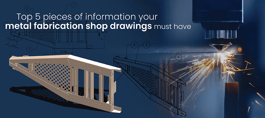
Top 5 pieces of information your metal fabrication shop drawings must have
1. Clear design visualization
All shop drawings must have clear views as per ISO drawing standards and guidelines and should follow GMPs (Good manufacturing practice). Most part drawings for metal fabrication use front view, top view and side view, drawn using scaling and projection methods. Sometimes, the designer uses sections to enhance design clarity and show precise dimensions to develop required shapes and sizes.
Part drawings ‘exploded views’ with BOM balloons around each part, and sub-assemblies are also created to show how each part fits in the assembly. These drawings also show information for fasteners and weldments and help decide the sequence of assembling each part step-by-step. For sheet metal parts, besides ISO views, fabricators also need flat pattern views in DXF format for direct machining.
2. Precise dimensions with tolerance values
All shop drawings must have clear geometric dimensions and tolerances mentioned to ensure economical use of metal and reduce scrap. CAD engineers must follow standard geometric dimensioning and tolerances (GD&T) while including such critical information in drawing files.
These drawing files will eventually become blueprints for the product to be manufactured down the line. It is thus imperative to include information like raw materials, processes, parts to be machined, and manufacturing process to be followed.
3. Information regarding critical manufacturing processes
Besides design dimensions, shop drawings also specify the exact specifications of raw materials to be used and quality standards to be followed. There are quality notes included as footnotes with layers on drawings in CAD platform. This helps the reviewer/designer to mark comments and keep track. Special requirements that are critical to quality are also mentioned here.
For repetitive features like holes and slots, tables are made in shop drawings to create them in one go, on a single machine. It also helps the designer and the manufacturer to improve overall productivity during sheet metal manufacturing.
In case of surface treatments, critical information pertains to grain direction, draft angles for casting and machining, allowances, etc. These aspects are critical from the manufacturing perspective to ensure that the metal piece doesn’t undergo any significant changes.
4. Clear, detailed BOMs
For any small or a large assembly, BOM tables are necessary for accuracy. The shop floor takes all decisions, such as managing inventory and other manufacturing processes at vendor locations and in-house as well. For instance, there are various stations on the shop floor that are run by operators with varying skill set. With BOMs, shop floor engineers can efficiently allocate skilled and semi-skilled labor and tooling.
5. Information for revisions, company name, vendor name
All manufacturing shop drawings have title blocks with the manufacturer’s name, revisions, name of parts, assembly number, projection method, tolerance, scale of drawings and sheet number. Additionally, the shop drawings should also have the raw material supplier’s information.
In advanced level MBD techniques of 3D CAD modeling, the files also include metadata for parts and assemblies. It minimizes conflicts between stakeholders as a single source of truth is formed.
Conclusion
It is a fact that costs of metal are rising and so is the demand of metal products for various industries. Manufacturers cannot afford an increase in scrap due to rework and design misinterpretation, and stay profitable at the same time. For this, they must ensure that metal fabrication shop drawings are detail-rich and accurate.
It is a CAD engineer’s duty to ensure that all necessary information is included in a single draft of metal shop drawings. Without that, metal fabricators get caught in a vicious cycle of rework and re-manufacturing resulting in significant delays. While CAD platforms enhance the detailing in each drawing, having a solid foundation of fabrication processes gives them a winning edge.
About Author:
Usha B. Trivedi is an engineer and she contributes in-depth articles for mechanical and industrial equipment designs, furniture designs, and the fabrication sector. Her contributions are primarily focused on enabling engineering professionals, furniture manufacturers, and fabricators to optimize design outcomes through CAD and CAE tools.